

Re-routing a Segment of Salt Creek for Stream Restoration
By Erin Pande, PWS, CFM; Drew Kustusch, PE, CFM
The successful design and construction of the bypass channel for the Preserve at Oak Meadows project facilitated 700,000 cu yd (535,188 cu m) of earthwork and restoration of Salt Creek.
The Preserve at Oak Meadows located in the Villages of Addison and Wood Dale, Illinois, is owned and operated by the Forest Preserve District of DuPage County. It contained the 18-hole Oak Meadows Golf Course and the Maple Meadows East-9, which together consisted of 27 holes of golf on a continuous 288-acre (1.17-km2) property, previously referred to as the Oak Meadows Golf Preserve. It is a picturesque course with Oak/Hickory woodlands and open savannas with Salt Creek meandering through it. In February 2009, the 86-year-old 45,000-sq ft (4,180-sq m) clubhouse at the course was lost to fire damage. This loss, combined with the increase in the frequency of significant flood damage, brought the Oak Meadows Golf Preserve to a critical juncture.
Recurring flood damage to playing areas as well as aging features on a course were eroding the customer base and lowering the operational revenue. In 2012, Engineering Resource Associates, Inc. (ERA) and Martin Design Partnership, Ltd. developed a master plan for the redevelopment of Oak Meadows Golf Preserve that included:
- Reconfiguration of the 18-hole Oak Meadows golf course and the 9-hole Maple Meadows golf course to one, 18-hole course.
- Regraded greens with improved flood protection to decrease loss of playability from flooding.
Elevation, removal and relocation of golf cart bridges. - In-stream modifications to improve water quality through riffles, a-jacks and sheet pile wall removal, and rock/log toe and fabric encapsulating soil lifts.
- Wetland creation, wetland restoration and riparian/prairie/savanna restoration; and expanded floodplain storage.
While the project as a whole was immense at 700,000 cu yd (535,188 cu m) of earthwork and the sediment and erosion control methods that were used throughout the site were extensive, this article will focus on the stream bypass methods used to construct the in-stream aspects of the project only.
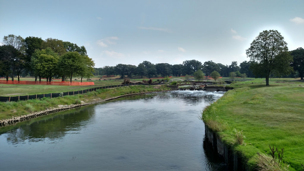
Within the project limits, there were two low-head dams that spanned Salt Creek (Figure 1). In addition to negatively impacting water quality, the dams were a physical obstacle for migrating aquatic life and dangerous for paddlers. A-jacks and sheet pile walls also contributed to poor water quality and lack of habitat. The plan proposed removal of both dams and existing bank stabilization measures. Following removal, stream channel and bank stabilization was necessary. This included the addition of pool and riffle sequences, improved substrate, in-stream habitat structure and streambank stabilization.
A temporary bypass channel for Salt Creek was used to facilitate efficient construction. The bypass channel was sized to convey the one-year, 24-hour storm event and all smaller storm events. This design storm was not a regulatory requirement, but rather was selected as a balance between the cost of additional channel excavation and the cost of construction site and scheduling impacts due to overtopping. A cofferdam was placed in Salt Creek channel at the upstream and downstream tie-in locations for the bypass channel. The crests of the cofferdams were designed at the one-year storm elevations. For this design, the one-year flow was determined using an extrapolation from Salt Creek Full Equation model flow data and was determined to be 770 cu ft/second (21.8 cu m/second).
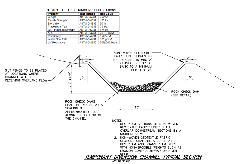
The proposed bypass channel was trapezoidal with a 15 ft (4.572 m) wide bottom and 2:1 side slopes and 0.75 mi (1.2 km) long. The earthwork quantity associated with the bypass channel was approximately 19,255 cu yd (14,722 cu m). The channel was lined with a non-woven polyethylene geotextile fabric with a Manning’s n value of approximately 0.025 in order to increase the conveyance capacity as compared to a bare-earth or rock-lined channel. The fabric was secured by burying the upstream end of each segment of fabric and overlapping the downstream end over the subsequent segment. The bypass channel design was also input into the modified existing river model in the USACOE’s Hydrologic Engineering Center River Analysis System (HEC-RAS).
Due to the requirements of the stormwater certification issued by DuPage County, no increase greater than 0.1 ft (0.03 m) as compared to the regulatory FEMA Flood Insurance Study elevations along the river corridor was allowed during or after construction. The results with the included bypass channel for the 10-year and 100-year flows showed maximum increases in elevation of 0.03 ft (0.009 m) and 0.02 ft (0.006 m), respectively, which was considered negligible, and maximum decreases in elevation of 1.03 ft (0.31 m) and 0.62 ft (0.19 m), respectively. One-year flows were also modeled in the bypass channel to verify that the channel had sufficient capacity. The cross-sections from the HEC-RAS output showed that the one-year flows would be contained within the proposed bypass channel. Plan and profile and cross-section sheets for the proposed bypass channel were prepared and were included in the final engineering plan set (Figure 2).
Permits were required from the U.S. Army Corps of Engineers, Illinois Department of Natural Resources Office of Water Resources, DuPage County Stormwater Management, Kane-DuPage Soil and Water Conservation District and Villages of Addison and Wood Dale. Pre-application meetings were held with all agencies concurrently to determine the best means and methods for constructing the in-stream restoration.
The construction sequence for installation of the temporary bypass channel and dewatering of Salt Creek is below:
- Excavate bypass channel but leave earthen berms at both upstream and downstream ends.
- Stabilize bypass channel with geotextile liner custom fabricated and field welded.
- Install concrete blocks in the energy dissipation zone at the downstream bypass channel discharge in order to reduce velocities and distribute flows prior to the water entering the downstream channel.
- Install concrete blocks in the energy dissipation zone at the upstream bypass channel location to reduce velocities where the natural channel meets the fabric-lined channel and minimize erosion potential.
- Place bypass channel cofferdam immediately downstream of downstream earthen plug and immediately upstream of upstream earthen plug.
- Excavate downstream existing earthen plug to tie bypass channel into the river and finish stabilizing downstream bypass channel with liner.
- Excavate upstream earthen plug to tie bypass channel into the river and finish stabilizing upstream bypass channel
with liner. - Remove downstream bypass channel cofferdam.
- Remove upstream bypass channel cofferdam.
- Install in-stream sheet pile cofferdam just downstream of upstream bypass channel tie-in.
- Install backflow sheet pile just upstream of bypass channel downstream tie-in.
- Install in-stream sump pit and dewater isolated work zone within existing
river channel. - Install energy dissipation measures in the coffered portion of the existing river channel just downstream of the upstream sheet pile.
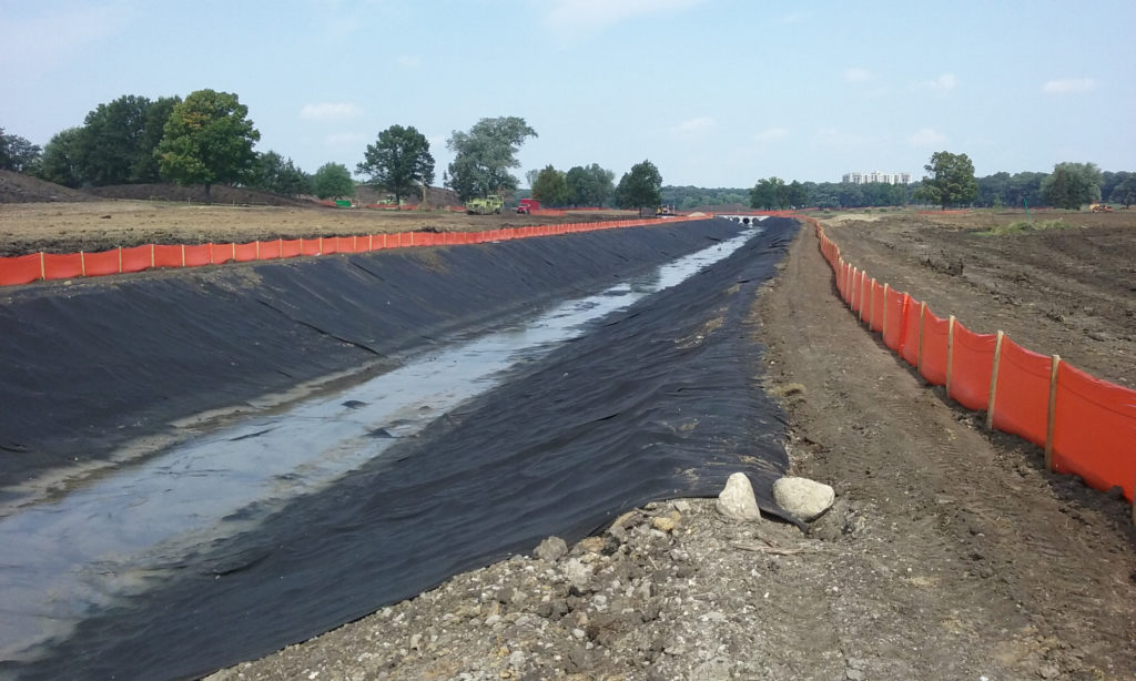
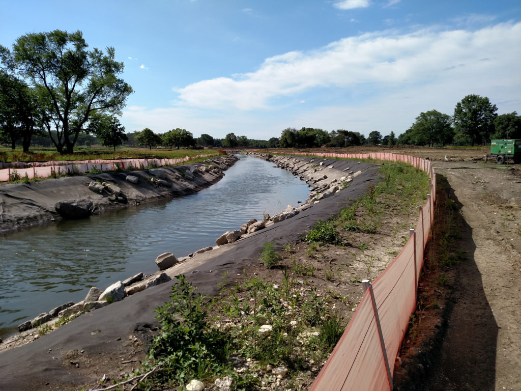
The temporary bypass channel functioned generally according to plan during construction (Figure 3). However, modifications were needed as the geotextile fabric began to float due to unanticipated groundwater uplift pressure beneath the channel. Angular and subangular boulders ranging in diameter from 18 in to 36 in were placed on the geotextile at high stress locations to provide additional weight over the fabric and prevent it from continuing to float and tear (Figure 4).
The temporary bypass channel allowed for the removal of the low-head dams, sheet pile walls and a-jacks; construction of the pool and riffle sequences, improved substrate, in-stream habitat structure and streambank stabilization.
Upon completion of the in-stream work and installation of permanent erosion control measures the stream was returned back to Salt Creek. The following is the sequence used for diverting the flow back into Salt Creek.
- Remove in-stream dewatering sump pit.
- Remove downstream sheet pile from
Salt Creek. - Remove upstream sheet pile from Salt Creek.
- Install sheet pile cofferdam at upstream bypass channel to divert flow back into
the river. - Dewater and install embankment plug at the upstream end of the bypass channel.
- Install sheet pile cofferdam at downstream bypass channel.
- Dewater and install embankment plug at the downstream end of the bypass channel.
- Remove sheet pile cofferdam at upstream and downstream bypass channel tie-ins.
- Perform final stabilization of in-stream banks at upstream and downstream bypass channel tie-ins.
- Remove energy dissipation measures at upstream and downstream bypass channel tie-ins.
- Remove bypass channel geotextile liner.
- Final grade temporary bypass channel according to plans.
- Install temporary cover crop, permanent seed, temporary erosion control blanket
and native plant plugs after final grading is complete.
Following completion of the Preserve at Oak Meadows project in 2017, the course has not experienced flooding that previously impacted playability. The methods described above allowed the contractor to isolate Salt Creek from upstream flow and restore the creek without releasing sediment downstream. The resulting project restored 6,585 ft of Salt Creek, created 25 acres of wetland and 35 acre-feet of additional floodplain storage.
Although ultimately a success, the main constructability issue with the bypass channel was the uplift, detachment and tearing of the geotextile fabric. While only two of the 51 soil borings completed onsite contained groundwater, this should have been considered due to the multi-year length of the project and, therefore, the probability of a period of high groundwater. Design modifications for future bypass channels may include specification of a geotextile fabric with higher permittivity to allow groundwater pressure relief into the channel, additional burial depth of the upstream end of each fabric segment and installation of boulders as additional weight at regular intervals along the channel.
About the Experts
Erin Pande, PWS, CFM, is a Professional Wetland Scientist and Certified Floodplain Manager at Engineering Resource Associates, Inc. She has worked in the stream and wetland restoration field for 20 years. She performs natural area assessments and designs and implements streambank and shoreline stabilization, natural area restoration and water quality best management practice projects.
Andrew Kustusch, PE, CFM, is a Certified Floodplain Manager and a licensed professional engineer in the states of Colorado and Illinois. He currently serves as a project engineer, erosion control designer and green infrastructure specialist with Engineering Resource Associates, Inc.


